
VISION – Status display
Emitter – VISION V, VISION VXL, VISION MXL
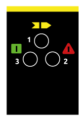
| 1 Yellow LED | 2 Red LED | 3 Green LED | Meaning |
| ⊗ | ⊗ | ⊗ | System power-on – Initial TEST |
| ⊗ | ⊗ | ⊗ | TEST condition |
| ⊗ | ⊗ | ⊗ | GUARD condition. Low range |
Emitter – VISION VX
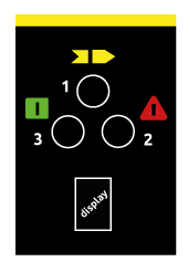
| 1 Yellow LED | 2 Red LED | 3 Green LED | Display | Meaning |
| ⊗ | ⊗ | ⊗ | 8 | System power-on – Initial TEST |
| ⊗ | ⊗ | ⊗ | L / H | TEST condition |
| ⊗ | ⊗ | ⊗ | L | GUARD condition. Low range |
| ⊗ | ⊗ | ⊗ | H | GUARD condition. High range |
| ⊗ | ⊗ | ⊗ | CODE | FAIL condition – The type of fault is identified by the code number on display. See next “fail condition table” |
Fail condition
| Display code | Meaning |
| F – P | Range selection incorrect or modified |
| F – A | Internal error (add-on board) |
| F – 3 | Internal error (master board) |
| F – 4 | Internal error |
Receiver – VISION V, VISION VXL
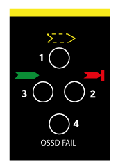
| 1 Yellow LED | 2 Red LED | 3 Green LED | 4 OSSD FAIL LED | Meaning |
| ⊗ | ⊗ | ⊗ | ⊗ | System power-on – Initial TEST |
| ⊗ Blinking | ⊗ | ⊗ | ⊗ | Manual/automatic restart with feedback enabled/disabled. (VISION VXL models only) |
| ⊗ | ⊗ | ⊗ | ⊗ | BREAK condition |
| ⊗ | ⊗ | ⊗ | ⊗ | Received beam signal intensity is weak |
| ⊗ | ⊗ | ⊗ | ⊗ | GUARD condition |
Receiver – VISION VX
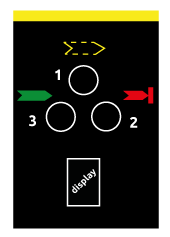
| 1 Yellow LED | 2 Red LED | 3 Green LED | Display | Meaning |
| ⊗ | ⊗ | ⊗ | 8 | System power-on – Initial TEST |
| ⊗ | ⊗ | ⊗ | C | C displayed for 10 sec. – Manual restart with feedback disabled (not for slave models) |
| ⊗ | ⊗ | ⊗ | C | C displayed for 10 sec. – Manual restart with feedback enabled (not for slave models) |
| ⊗ | ⊗ | ⊗ | C | C displayed for 10 sec. – Automatic restart with feedback disabled (not for slave models) |
| ⊗ | ⊗ | ⊗ | C | C displayed for 10 sec. – Automatic restart with feedback enabled (not for slave models) |
| ⊗ | ⊗ | ⊗ | – | BREAK condition |
| ⊗ | ⊗ | ⊗ | D | BREAK condition with weak signal |
| ⊗ | ⊗ | ⊗ | – | CLEAR condition. Waiting for restart (not for slave models) |
| ⊗ | ⊗ | ⊗ | D | CLEAR condition with weak signal (not for slave models) |
| ⊗ Blinking | ⊗ | ⊗ | – | Master in CLEAR, Slave in BREAK conditions (Master Models only) |
| ⊗Blinking | ⊗ | ⊗ | D | Master in CLEAR, Slave in BREAK conditions with weak signal.(Master Models only) |
| ⊗ | ⊗ | ⊗ | – | GUARD condition |
| ⊗ | ⊗ | ⊗ | D | GUARD condition with weak signal |
| ⊗ | ⊗ | ⊗ | Receiver initialization | |
| ⊗ | ⊗ | ⊗ | Code | FAIL condition – The type of fault is identified by the code number on display. See next “Fail condition tablel” |
Fail condition
| Display code | Meaning |
| O | Overload of the OSSD static outputs |
| F – C | Customer configuration rejected |
| F – 2 | OSSD erroneously connectedt o 24VDC |
| F – E | External Feedback contactors missed |
| F – 3 | Internal error |
| F – 4 | |
| F – A | |
| F – 6 | OSSD1 – OSSD2 short–circuit |
| F – 0 | Overload of the OSSD static outputs (only for MASTER models) |
| F – 5 | OSSD static outputs error |
| F – 1 | Interfering dangerous Emitter detected. The receiver is able to receive simultaneously the beams from two different Emitters (30 sec) |
| F – U | SLAVE connections incorrect (only for MASTER models) |
| F – H | User configuration changed without system restart (only for MASTER models) |
Receiver – VISION MXL
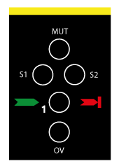
| 1 Three colour LED | S1 LED | S2 LED | MUT LED | OV LED | Meaning |
| ⊗ | ⊗ | ⊗ | ⊗ | ⊗ | System power-on – Initial TEST |
| ⊗ | ⊗ | ⊗ | ⊗ | ⊗ | First 5 s. Manual restart with Muting timeout = 30 s. |
| ⊗ | ⊗ | ⊗ | ⊗ | ⊗ | First 5 s. Manual restart with Muting timeout = 90 min. |
| ⊗ | ⊗ | ⊗ | ⊗ | ⊗ | First 5 s. Manual restart with Muting timeout = infinite |
| ⊗ | ⊗ | ⊗ | ⊗ | ⊗ | First 5 s. Automatic restart with Muting timeout = 30 s. |
| ⊗ | ⊗ | ⊗ | ⊗ | ⊗ | First 5 s. Automatic restart with Muting timeout = 90 min. |
| ⊗ | ⊗ | ⊗ | ⊗ | ⊗ | First 5 s. Automatic restart with Muting timeout = infinite. |
| ⊗ | ⊗ ⊗ Status | ⊗ ⊗ Status | ⊗ | ⊗ | BREAK condition |
| ⊗ | ⊗ | ⊗ | ⊗ | ⊗ | CLEAR condition. Waiting for restart |
| ⊗ | ⊗ ⊗ Status | ⊗ ⊗ Status | ⊗ | ⊗ | MUTING condition |
| ⊗ | ⊗ ⊗ Status | ⊗ ⊗ Status | ⊗ | ⊗ | GUARD condition |
| ⊗ | ⊗ ⊗ Status | ⊗ ⊗ Status | ⊗ | ⊗ | OVERRIDE condition |
| ⊗ | ⊗ ⊗ Status | ⊗ ⊗ Status | ⊗ | ⊗ Blinking | OVERRIDE request with BREAK |
| ⊗ | ⊗ ⊗ Status | ⊗ ⊗ Status | ⊗ | ⊗ Blinking | OVERRIDE request with S1 or S2 |
Configuration errors
| 1 Three colour LED | S1 LED | S2 LED | MUT LED | OV LED | Meaning |
| ⊗ Blinking | ⊗ Blinking | ⊗ Blinking | ⊗ | ⊗ | OSSD output incorrectly connected to 24VDC |
| ⊗ Blinking | ⊗ Blinking | ⊗ | ⊗ Blinking | ⊗ | Muting timeout incorrectly selected |
| ⊗ Blinking | ⊗ | ⊗ Blinking | ⊗ | ⊗ | Incorrect connection of pin FBK_K1K2/RESTART |
| ⊗ Blinking | ⊗ Blinking | ⊗ | ⊗ | ⊗ | Incorrect connection of pin OVERRIDE |
