
ADMIRAL – Status display
Emitter – All models
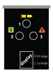
| 1 Yellow LED | 2 Red LED | 3 Green LED | Display | Meaning |
| ⊗ | ⊗ | ⊗ | 8 | System power-on – Initial TEST |
| ⊗ | ⊗ | ⊗ | L / H | TEST condition |
| ⊗ | ⊗ | ⊗ | L | GUARD condition. Low range |
| ⊗ | ⊗ | ⊗ | H | GUARD condition. High range |
| ⊗ | ⊗ | ⊗ | Code | FAIL condition – The type of fault is identified by the code number on display. See next “Fail condition tablel” |
Fail condition
| Display code | Meaning |
| F – P | Range selection incorrect or modified |
| F – A | Internal error (add-on board) |
| F – 3 | Internal error (master board) |
| F – 4 | Internal error |
Receiver – ADMIRAL AD
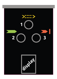
| 1 Yellow LED | 2 Red LED | 3 Green LED | Display | Meaning |
| ⊗ | ⊗ | ⊗ | 8 | System power-on – Initial TEST |
| ⊗ | ⊗ | ⊗ | – | BREAK condition |
| ⊗ | ⊗ | ⊗ | – | Received beam signal intensity is weak |
| ⊗ | ⊗ | ⊗ | – | GUARD condition |
| ⊗ | ⊗ | ⊗ | Code | FAIL condition – The type of fault is identified by the code number on display. See next “Fail condition table” |
Fail condition
| Display code | Meaning |
| O | Overcurrent on one or both outputs (OSSD) |
| F – 1 | Detection of a hazardous interfering Emitter condition. The Receiver is able to receive the beams emitted by two different Emitters at the same time. (This fault is displayed for at least 30 seconds) |
| F – 2 | Connection of load between static outputs (OSSD) and the positive power supply line (+ 24 Vdc) |
| F – 4 | Internal failure relating to the microcontroller boards |
| F – 5 | Erroneous connection of static outputs (OSSD) |
| F – 6 | Probable short circuit between the two outputs (OSSD) |
Receiver – ADMIRAL AX
| 1 Yellow LED | 2 Red LED | 3 Green LED | Display | Meaning |
| ⊗ | ⊗ | ⊗ | 8 | System power-on – Initial TEST |
| ⊗ | ⊗ | ⊗ | C | C displayed for 10 sec. – Manual restart with feedback disabled |
| ⊗ | ⊗ | ⊗ | C | C displayed for 10 sec. – Manual restart with feedback enabled |
| ⊗ | ⊗ | ⊗ | C | C displayed for 10 sec. – Automatic restart with feedback disabled |
| ⊗ | ⊗ | ⊗ | C | C displayed for 10 sec. – Automatic restart with feedback enabled |
| ⊗ | ⊗ | ⊗ | – | BREAK condition |
| ⊗ | ⊗ | ⊗ | D | BREAK condition with weak signal |
| ⊗ | ⊗ | ⊗ | – | CLEAR condition. Waiting for restart |
| ⊗ | ⊗ | ⊗ | D | CLEAR condition with weak signal |
| ⊗ Blinking | ⊗ | ⊗ | – | Master in CLEAR, Slave in BREAK conditions (Master Models only) |
| ⊗ Blinking | ⊗ | ⊗ | D | Master in CLEAR, Slave in BREAK conditions with weak signal.(Master Models only) |
| ⊗ | ⊗ | ⊗ | – | GUARD condition |
| ⊗ | ⊗ | ⊗ | D | GUARD condition with weak signal |
| ⊗ | ⊗ | ⊗ | Receiver initialization | |
| ⊗ | ⊗ | ⊗ | Code | FAIL condition – The type of fault is identified by the code number on display. See next “Fail condition table” |
Fail condition
| Display code | Meaning |
| O | Overload of the OSSD static outputs |
| F – C | Customer configuration rejected |
| F – 2 | OSSD erroneously connectedt o 24VDC |
| F – E | External Feedback contactors missed |
| F – 3 | Internal error |
| F – 4 | |
| F – A | |
| F – 6 | OSSD1 – OSSD2 short–circuit |
| F – 0 | Overload of the OSSD static outputs (only for MASTER models) |
| F – 5 | OSSD static outputs error |
| F – I | Interfering dangerous Emitter detected. The receiver is able to receive simultaneously the beams from two different Emitters (30 sec) |
| F – U | SLAVE connections incorrect (only for MASTER models) |
| F – H | User configuration changed without system restart (only for MASTER models) |
Receiver – ADMIRAL AX BK
| 1 Yellow LED | 2 Red LED | 3 Green LED | Display | Meaning |
| ⊗ | ⊗ | ⊗ | 8 | System power-on – Initial TEST |
| ⊗ | ⊗ | ⊗ | C | C displayed for 10 sec. – Blanking S.O.P.O. (Without Object Presence Obligation) Mode A1 |
| ⊗ | ⊗ | ⊗ | C | C displayed for 10 sec. – Blanking S.O.P.O. (Without Object Presence Obligation) Mode A2 |
| ⊗ Blinking | ⊗ | ⊗ | C | C displayed for 10 sec. – Blanking S.O.P.O. (Without Object Presence Obligation) Mode A3 |
| ⊗ | ⊗ | ⊗ | C | C displayed for 10 sec. – Blanking C.O.P.O. (With Object Presence Obligation) Mode B1 |
| ⊗ | ⊗ | ⊗ | C | C displayed for 10 sec. – Blanking C.O.P.O. (With Object Presence Obligation) Mode B2 |
| ⊗ | ⊗ | ⊗ | – | BREAK condition |
| ⊗ | ⊗ | ⊗ | D | BREAK condition with weak signal |
| ⊗ | ⊗ | ⊗ | B | BREAK condition in case of Mode B1/B2 blanking |
| ⊗ | ⊗ | ⊗ | B | BREAK condition in case of Mode B1/B2 blanking with weak signal |
| ⊗ | ⊗ | ⊗ | J | Master in CLEAR, Slave in BREAK conditions (Master Models only) |
| ⊗ | ⊗ | ⊗ | J | Master in CLEAR, Slave in BREAK conditions with weak signal.(Master Models only) |
| ⊗ | ⊗ | ⊗ | – | GUARD condition |
| ⊗ | ⊗ | ⊗ | – | GUARD condition with weak signal |
| ⊗ | ⊗ | ⊗ | R | Active blanking conditions |
| ⊗ | ⊗ | ⊗ | R | Active blanking conditions with weak signal |
| ⊗ | ⊗ | ⊗ | Receiver initialization | |
| ⊗ | ⊗ | ⊗ | Code | FAIL condition – The type of fault is identified by the code number on display. See previous “Fail condition table” |

