
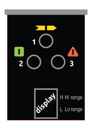
ADMIRAL – Display stato di funzionamento
Emettitore – Tutti i modelli
| 1 LED Giallo | 2 LED Rosso | 3 LED Verde | Display | Significato |
| ⊗ | ⊗ | ⊗ | 8 | Accensione del sistema – TEST iniziale |
| ⊗ | ⊗ | ⊗ | L / H | Condizione di TEST |
| ⊗ | ⊗ | ⊗ | L | Condizione di GUARD. Bassa portata |
| ⊗ | ⊗ | ⊗ | H | Condizione di GUARD. Alta portata |
| ⊗ | ⊗ | ⊗ | Codice | Condizione di guasto – Il tipo di guasto viene identificato dal codice numerico che appare ne display – Vedere “la tabella dei guasti” illustrata di seguito |
Tabella guasti
| Codice sul display | Significato |
| F – P | Portata selezionata non corretta o modificata |
| F – A | Errore interno (scheda aggiuntiva) |
| F – 3 | Errore interno (Scheda base) |
| F – 4 | Errore interno |
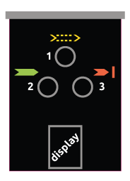
Ricevitore – ADMIRAL AD
| 1 LED Giallo | 2 LED Rosso | 3 LED Verde | Display | Significato |
| ⊗ | ⊗ | ⊗ | 8 | Accensione del sistema – TEST iniziale |
| ⊗ | ⊗ | ⊗ | – | Condizione di BREAK |
| ⊗ | ⊗ | ⊗ | – | Intensità del segnale debole |
| ⊗ | ⊗ | ⊗ | – | Condizione di GUARD condition |
| ⊗ | ⊗ | ⊗ | Codice | Condizione di guasto – Il tipo di guasto viene identificato dal codice numerico che appare ne display – Vedere “la tabella dei guasti” illustrata di seguito |
Tabella guasti
| Codice sul display | Significato |
| O | Condizione di sovracorrente su una oppure su entrambe le uscite (OSSD) |
| F – 1 | Rilevata condizione pericolosa di Emettitore interferente. Il Ricevitore è in grado di ricevere contemporaneamente i raggi emessi da due diversi Emettitori. (Il rilevamento di questa anomalia viene visualizzato per un tempo minimo pari a 30 secondi) |
| F – 2 | Collegamento del carico tra le uscite statiche (OSSD) e la linea di alimentazione positiva (+ 24 Vdc) |
| F – 4 | Guasto interno relativo alle schede a microcontrollore |
| F – 5 | Collegamento errato delle uscite statiche (OSSD) |
| F – 6 | Probabile corto circuito tra le due uscite (OSSD) |
Ricevitore – ADMIRAL AX
| 1 LED Giallo | 2 LED Rosso | 3 LED Verde | Display | Significato |
| ⊗ | ⊗ | ⊗ | 8 | Accensione del sistema – TEST iniziale |
| ⊗ | ⊗ | ⊗ | C | C acceso per 10 sec: Restart manuale con feedback disabilitato |
| ⊗ | ⊗ | ⊗ | C | C acceso per 10 sec: Restart manuale con feedback abilitato |
| ⊗ | ⊗ | ⊗ | C | C acceso per 10 sec: Restart automatico con feedback disabilitato |
| ⊗ | ⊗ | ⊗ | C | C acceso per 10 sec: Restart automatico con feedback abilitato |
| ⊗ | ⊗ | ⊗ | – | Condizione di BREAK |
| ⊗ | ⊗ | ⊗ | D | Condizione di BREAK con segnale debole |
| ⊗ | ⊗ | ⊗ | – | Condizione di CLEAR. Barriera in attesa di Restart |
| ⊗ | ⊗ | ⊗ | D | Condizione di CLEAR con segnale debole |
| ⊗ Lampeggiante | ⊗ | ⊗ | – | Barriera Master in condizione di CLEAR, barriera Slave in condizione di BREAK. (Solo modelli Master) |
| ⊗ Lampeggiante | ⊗ | ⊗ | D | Barriera Master in condizione di CLEAR, barriera Slave in condizione di BREAK con segnale debole. (Solo modelli Master) |
| ⊗ | ⊗ | ⊗ | – | Condizione di GUARD |
| ⊗ | ⊗ | ⊗ | D | Condizione di GUARD con segnale debole |
| ⊗ | ⊗ | ⊗ | Inizializzazione del ricevitore | |
| ⊗ | ⊗ | ⊗ | Codice | Condizione di guasto – Il tipo di guasto viene identificato dal codice numerico che appare ne display – Vedere “la tabella dei guasti” illustrata di seguito |
Tabella guasti
| Codice Display | Significato |
| O | Condizione di sovracorrente su una oppure su entrambe le uscite (OSSD) |
| F – C | Configurazione utente rifiutata |
| F – 2 | Collegamento del carico tra le uscite statiche (OSSD) e la linea di alimentazione positiva (+ 24 Vdc) |
| F – E | Feedback contattori esterni mancante |
| F – 3 | Errore interno |
| F – 4 | |
| F – A | |
| F – 6 | Cortocircuito OSSD1 – OSSD2 |
| F – 0 | Rilevato sovraccarico OSSD durante la configurazione (solo modelli MASTER) |
| F – 5 | Guasto uscite statiche OSSD |
| F – I | Rilevata condizione pericolosa di emettitore interferente. Il ricevitore è in grado di ricevere contemporaneamente i raggi emessi da due diversi Emettitori. (30 sec) |
| F – U | Collegamenti SLAVE errati (solo modelli MASTER) |
| F – H | Variata configurazione da utente senza aver riavviato il sistema (solo modelli MASTER) |
Ricevitore – ADMIRAL AX BK
| 1 LED Giallo | 2 LED Rosso | 3 LED Verde | Display | Significato |
| ⊗ | ⊗ | ⊗ | 8 | Accensione del sistema – TEST iniziale |
| ⊗ | ⊗ | ⊗ | C | C acceso per 10sec: Blanking S.O.P.O. (Senza Obbligo Presenza Oggetto) Modo A1 |
| ⊗ | ⊗ | ⊗ | C | C acceso per 10sec: Blanking S.O.P.O. (Senza Obbligo Presenza Oggetto) Modo A2 |
| ⊗ Lampeggiante | ⊗ | ⊗ | C | C acceso per 10sec: Blanking S.O.P.O. (Senza Obbligo Presenza Oggetto) Modo A3 |
| ⊗ | ⊗ | ⊗ | C | C acceso per 10sec: Blanking C.O.P.O. (Con Obbligo Presenza Oggetto) Modo B1 |
| ⊗ | ⊗ | ⊗ | C | C acceso per 10sec: Blanking C.O.P.O. (Con Obbligo Presenza Oggetto) Modo B2 |
| ⊗ | ⊗ | ⊗ | – | Condizione di BREAK |
| ⊗ | ⊗ | ⊗ | D | Condizione di BREAK con segnale debole |
| ⊗ | ⊗ | ⊗ | B | Condizione di BREAK in caso di modalità blanking B1/B2 |
| ⊗ | ⊗ | ⊗ | B | Condizione di BREAK in caso di modalità blanking B1/B2 con segnale debole |
| ⊗ | ⊗ | ⊗ | J | Barriera Master in condizione di CLEAR, barriera Slave in condizione di BREAK. (Solo modelli Master) |
| ⊗ | ⊗ | ⊗ | J | Barriera Master in condizione di CLEAR, barriera Slave in condizione di BREAK con segnale debole. (Solo modelli Master) |
| ⊗ | ⊗ | ⊗ | – | Condizione di GUARD |
| ⊗ | ⊗ | ⊗ | – | Condizione di GUARD con segnale debole |
| ⊗ | ⊗ | ⊗ | R | Condizione di blanking attiva |
| ⊗ | ⊗ | ⊗ | R | Condizione di blanking attiva con segnale debole |
| ⊗ | ⊗ | ⊗ | Inizializzazione del ricevitore | |
| ⊗ | ⊗ | ⊗ | Codice | Condizione di guasto – Il tipo di guasto viene identificato dal codice numerico che appare ne display – Vedere “la tabella dei guasti” illustrata in precedenza |

