
Simplified method for estimating the quantifiable part of the PL
After having chosen the category, verified that CCF scoring has been respected (for redundant architectures), found MTTFD, and DC values, the PL and the PFHD can be derived directly from table K.1 of the Standard.
The values of table K.1 have been computed by applying Markov analisys to the designated architectures of the 5 categories. Therefore, if the simplified method of the Standard is used, it is not possible to make exceptions regarding the Categories. The values of table K.1 have been calculated assuming that:
- Mission time = 20 years
- Constant failure rate throughout the mission time
- For Category 2: The test frequency is at least 100 times higher than the request frequency of the safety function and the MTTFD of the test channel is greater than half the MTTFD of the functional channel
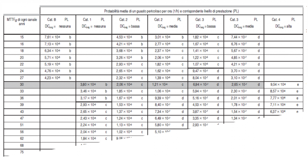
Table K.1 is read as follows:
The calculated MTTFD value is identified in a row of the left column and, after identifying the column corresponding to the implemented Category and the calculated DC, the PL and the PFHD value are found.
If it is needed only the PL value, then the graph of figure 5 of the standard can be used.
The combination of category and DC identifies one of the seven columns; the calculated MTTFD range determines which part of the column to consider. The corresponding PL value can then be read directly on the left side of the graph
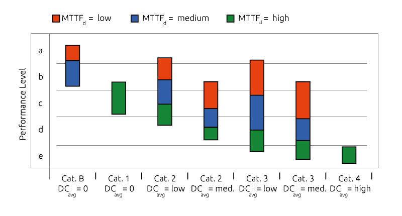
Fig. 12 – ISO 13849-1 – Figure 5
It may happen that the part of the column chosen includes two or three possible PL values (e.g in the case of Cat. 3, DC = medium and MTTFD = low, the following three values are possible: PL b, PL c, PL d) in these cases, table K.1 is used to get the correct PL value. As can be seen from Figure 5 for each Performance Level specified are available different choices. As an example from Table 5*it can be seen that for a system having PL of “c” the following five alternatives are possible:
- Category 3 with MTTFD = Low and DC medium
- Category 3 with MTTFD = Medium and DC low
- Category 2 with MTTFD = Medium and DC medium
- Category 2 with MTTFD = High and DC low
- Category 1 with MTTFD = High
Estimation of the PL based only on the Category information
This method is applicable only to the output subsystem of an SRP/CS. If for mechanical, hydraulic or pneumatic components (or components comprising a mixture of technologies) no application-specific reliability data are available, the machine manufacturer may evaluate the quantifiable aspects of the PL without any MTTFD calculation.
For such cases, the safety-related performance level (PL) is assured by the Category and by the measures against CCF. The next table shows the relationship between achievable PL and Categories.
| PFHd (1/h) | Cat. B | Cat. 1 | Cat. 2 | Cat. 3 | Cat. 4 | |
| PL a | 2*10-5 | * | 0 | 0 | 0 | 0 |
| PL b | 5*10-6 | * | 0 | 0 | 0 | 0 |
| PL c | 1,7*10-6 | – | *2 | *1 | 0 | 0 |
| PL d | 2,9*10-7 | – | – | – | *1 | 0 |
| PL e | 4,7*10-8 | – | – | – | – | *1 |
PLa and PLb can be achieved by using Category B; PLc can be achieved by using Category 1 or Category 2; PLd can be achieved by using Category 3; PLe can be achieved by using Category 4.
Furthermore:
- If Category 1 is used to obtain a PLc, it is essential:
- Determine, for the components involved in safety, the T10D value. This value can be determined on the basis of “proven in use” data provided by the machine manufacturer
- If Category 2 is used:
- Well tried safety principles and well tried components declared suitable by the component manufacturer for the particular application must be used
- MTTFD of the test channel must be at least 10 years
- DC must be low or medium
- Measures to control CCF must be in place
- If Category 3 is used:
- Well tried safety principles and well tried components must be used
- DC must be low or medium
- Measures to control CCF must be in place
- If Category 4 is used::
- Well tried safety principles and well tried components must be used
- DC must be high
- Measures to control CCF must be in place
Since formula E.1 of the standard cannot be used for the computation of the DC due to the unavailability of the MTTFD values, the DC must be derived simply as the arithmetic average of the individual DC values of the components of the output subsystem.
Proof that the component is “proven-in-use” is based on the failure analysis of the component over a long period of time used in the same specific configuration and for that particular application. There must be documented evidence that the probability of dangerous systematic failure of that component in that specific application is low enough for the required PL value.
The concept of a “proven in use” component is a concept of the IEC 61508 standard.
Combination of several SRC/PS to achieve the overall PL
The safety-related function may include one or more SRP/CSs, and several safety-related function may use the same SRP/CSs.
Where the safety-related function is made by a series connection of several SRP/CSs, e.g safety light curtains, control logics, power output, and if the PFHd values of all SRP/CSs are known, than the PHFD of the combined SRP/CS is the sum of all PFHD values of the N individual SRP/CSs.
The standard proposes two methods; a detailed one if for the single SRP/CS, in addition to the PL, also the PFHD is known and a simplified one if only the PL is available.
If the PFHD of the single subsystems are known, the total PFHD is equal to the sum of the PFHD values of each subsystems.
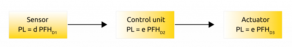
PFHD = PFHD1 + PFHD2 + PFHD3
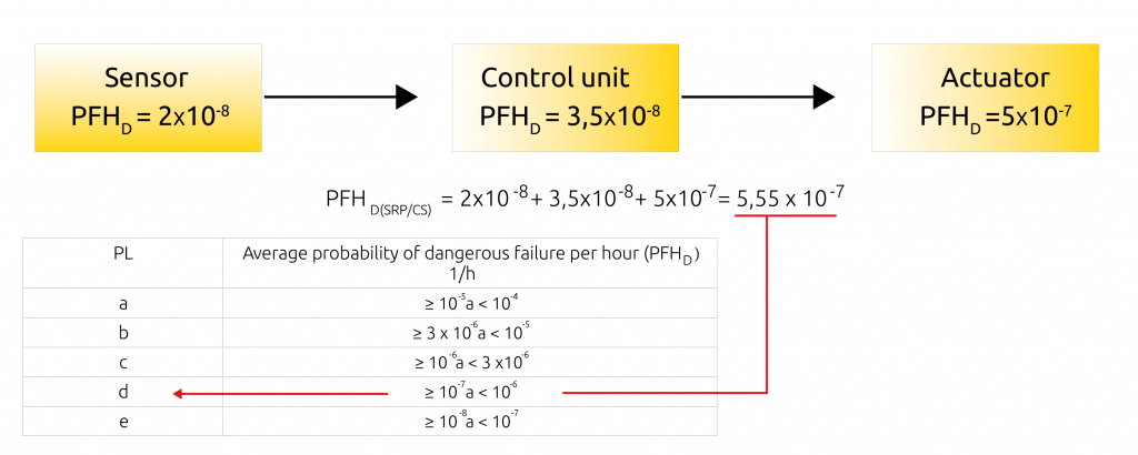
The PL of the SRP/CS is derived by entering the total PFHD value in the following table.
| PL | Average probability of dangerous failure (PFHD) |
| a | ≥ 10-5 to < 10-4 |
| b | ≥ 3 x 10⁻⁶ to < 10-5 |
| c | ≥ 10-6 to < 3 x10⁻⁶ |
| d | ≥ 10-7 to < 10-6 |
| e | ≥ 10-8 to < 10-7 |
Fig. 13 – Table 3 of ISO 13849-1 standard: Performance levels (PL)
Numerical Example:
The PL corresponding to the PFHD thus calculated is then limited by systematic constraints. The total PL cannot be greater than the lowest PL of all the subsystems that realize the safety function.
Limitation example:
The safety function consists of a Type 2 Photoelectric light curtain, PL c, a PL e control unit and a PL d drive
Summing the PFHD values it results:
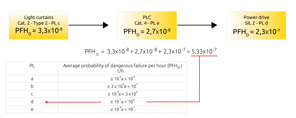
Entering 5.33×10⁻⁷ into the table, it follows that the resulting PL should be PL d
However, remembering the constraints due to systematic failures to which Type 2, photoelectric light curtains are subjected:
| ESPE TYPE | PL | SIL |
| 2 | a, b, c | 1 |
| 3 | a, b, c, d | 1, 2 |
| 4 | a, b ,c ,d | 1, 2, 3 |
Fig. 14 – Maximum PL for a safety function using safety light curtains
It comes that the maximum PL that can be reached by the safety function is limited to PL c
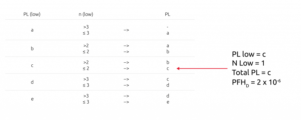
If it is known only the PL of the individual subsystems, an estimate PL of the combination can be derived by using the following table::
| PL (low) | n (low) | PL | |
| a | >3 ≤ 3 | --> | – |
| b | >2 ≤ 2 | --> | a |
| c | >2 ≤ 3 | --> | b |
| d | >3 ≤ 3 | --> | c |
| e | >3 ≤ 3 | --> | d |
Fig. 15 – Table for total PL computation
If the PFHd values of all individual SRP/CSs are not know: Locate the part with PL = PL low. Find the number of parts having PL = PL low
- Identify the part with the lowest PL is identified “PL (low)” first column
- Identify the number of parts with the lowest PL are identified “n (low)” second column
- The total PL is found in the corresponding row of the third column
Note: The PL obtained through this approximation refers to PFHD values that are in the middle of the range of the corresponding PL
In the proposed example of Fig. 15:
Subsystem interconnections
It is also necessary to give particular attention to the interfaces between subsystems:
The safety aspects related to the interfaces and connections between SRP/CS (e.g conductors or data communication bus) must be included in the PL of one of the associated Subsystems, otherwise connection errors must be excluded or negligible.
The cascade of safety subsystems must have compatible interfaces. Each subsystem output must be suitable for initiating the safe state of the downstream subsystem.

