安全指南
This safety guide refers to the set of rules governing the safety of machinery. In particular, this concerns the crucial family of standards under the umbrella of:
- ISO 13849 “Safety of machinery”
- IEC 61508 “ Functional safety of electrical / electronic / programmable electronic safety related systems” which impacts safety of machinery especially through IEC 62061 “Safety of machinery – Functional safety of safety-related electrical, electronic and programmable electronic control systems”
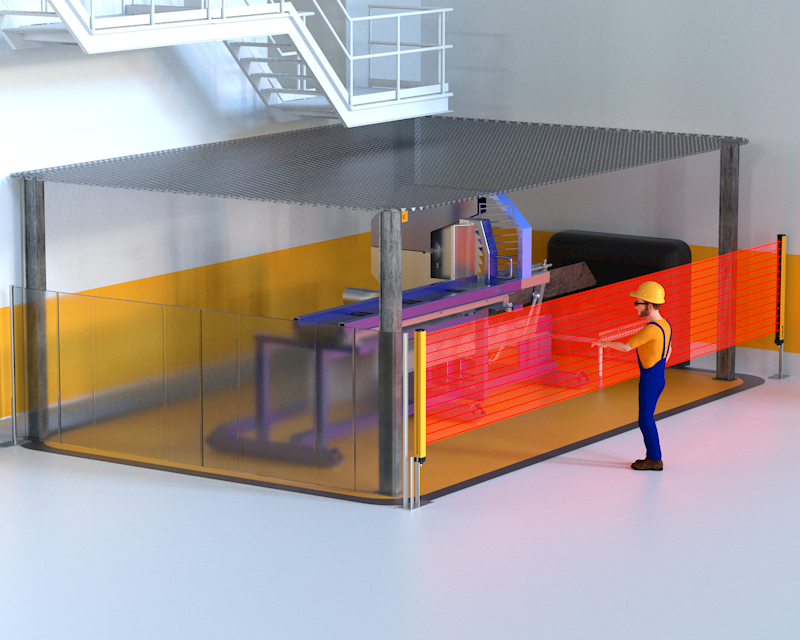
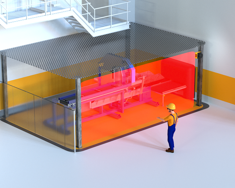
- IEC 61496 “Safety of machinery – Electro sensitive protective equipment”
Important statistical concepts related, in varying degrees, to probability of dangerous failure, are covered by machine safety, resulting in new classifications of safety-related control systems for machinery and protection devices. These include PLs (Performance Levels, for ISO) and SILs (Safety Integrity Levels, for IEC). PL and SIL come next to and in many ways replace the now familiar concept of category featuring in the ‘old’ EN 954-1.
The second edition of the Technical Specification IEC TS 62046 “Application of protective devices for the detection of the person”, is a useful guide for players who want to use electro-sensitive protective devices for the realization of control systems for machine safety.