

 Italiano
 English
 Deutsch
 Español
 Português
 한국어
한국어EN ISO 14119 Safety of machinery
Interlocking devices associated with guards – Principles for design and selection
New subdivision of the interlocking devices
Interlocking device interlock (ISO 14119:2013, § 3.1) – Mechanical, electrical or other type of device, the purpose of which is to prevent the operation of hazardous machine functions under specified conditions (generally as long as a guard is not closed).
Type 1 devices – Uncoded
These can be:
- Rotary cam
- Linear cam
- Hinge

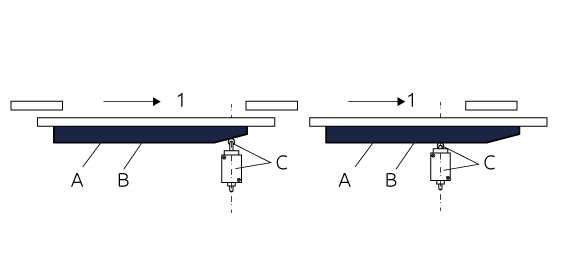
A: Movable guard
B: Actuator (cam)
C: Position switch
1: Opening direction
Type 2 – Coded
Coded actuator (ISO 14119:2013, § 3.13). Actuator which is specially designed (e.g. by shape) to actuate a certain position switch.
- Low level coded actuator: coded actuator for which 1 to 9 variations in code are available.
- Medium level coded actuator: coded actuator for which 10 to 1000 variations in code are available.
- High level coded actuator: coded actuator for which more than 1000 variations are available.
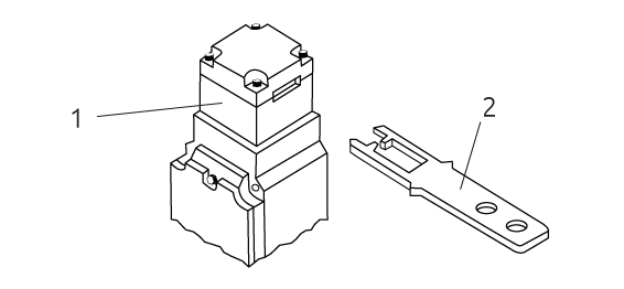
1: Position switch
2: Actuator (shaped tongue)
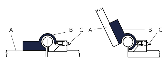
Type 3 – Unccoded
These can be:
- Inductive – Actuated by metal of the guard
- Magnetic – Actuated by uncoded magnet
- Capacitive – Ultrasonic or optical
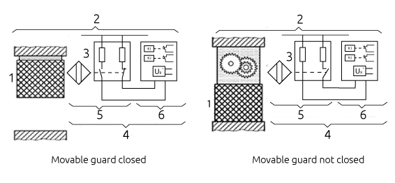
1: Movable guard
2: Interlocking device
3: Actuator (inductive, magnetic or capacitive)
4: Proximity switch
5: Actuating system
6: Output system
Type 4 – Coded
These can be:
- Magnetic – Actuated by coded magnet
- RFID
- Optical – Actuated by coded optics
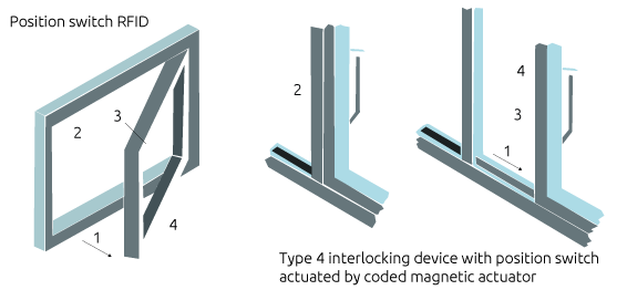
1: Opening direction
2: Type 4 interlocking device
3: coded RFID tag actuator
4: Movable guard
Type 5 – Coded
These can be: position switch with trapped key interlocking
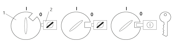
1: Switch
2: Bolt lock
Overall system stopping performance and access time (The gards distance)
The access time shall be calculated by using the distance between the hazard zone and the guard together with the approcach speed (see ISO 13855:2010 for typical values).
Logical series connection of interlocking devices
Logical series connection of interlocking device means for NC contacts wired in series or for NO contacts wired in parallel.
Up to now, for a logical series of NC contacts, it is considered a DC = 60%, allowing you to get a PL d (not a PL e). The masking of faults, could lead to a lower diagnostic coverage, so nothing.
Based on DC = λdd / λd (ratio of detected dangerous failures and total) can easily lead to a DC <60%.
Interlocking devices based on “fault exclusion”
The standard specifies that the maximum safety level reached by interlocking devices based on “fault exclusion” is generally PLd. In fact there is the possibility that a single mechanical failure resulting in the loss of the safety function.
For example a mechanical failure relating to the key (actuator), or some part of the mechanical device, can generate false information on the electrical contact output.
In some cases it is still possible reach the safety level PLe. These are cases of “fault exclusion for the guard locking”.
The safety level reached in these cases is not necessarily limited by the faults exclusion of the mechanical locking device.
However, specific requirements must be verified: the holding force specified (FZH) of the protection guard locking device must be sufficient to withstand static forces planned on locking bolt, it is also necessary to prevent any effect on the protection locking device determined by the forces dynamic due to movement of the protection guard.
Guard lock and Guard interlock
The standard emphasizes the fact that the interlock function and the lock function are two separate safety functions with PLR that can also be different (PLr Locking <PLr interlock).
Measures to prevent the defeat of the interlock device
Guards and protection devices of the machines should not be easy to by-pass or render non-operational (Directive 2006/42/EC §1.4.1). Measures required to minimize tampering.
Defeat (ISO 14119:2013, § 3.7 and § 3.8)
Defeat: action that makes interlocking devices inoperative or bypasses them with the result that a machine is used in a manner not intended by the designer or without the necessary safety measures.
Defeat in a reasonably foreseeable manner: defeat of an interlocking device either manually or by using readily available objects. Measures to reduce the defeat of interlocking devices may be adopted:
Prevent access to the elements which constitute the interlock device:
- Mouting out of reach, physical obstruction / shielding, Mounting in hidden position)
- Preventing substitution of the actuators using encoded interlocking devices
- Prevent disassembly or moving of the interlocking devices (welding, gluing, riveting, etc ..)
- Status monitoring or cyclic testing of the intelocking device
- Adding an additional interlock device with a different principle of implementation. In this case, you will testing diving the plausibility of the state of both devices
The table 3 of the standard ISO 14119:2013 specify the additional measures against defeating interlocking devices depending on type.
The anti-tampering measures in case of magnetic sensors low level encoding (MAGNUS)
Mandatory:
- Mouting out of reach places, or mounting recesses and not visible in the machine, or status monitoring
- Mounting the actuator so that it is difficult to remove
Advice:
- Second magnetic sensor
- Plausibility check of both sensors

