

 Italiano
 English
 Deutsch
 Español
 简体中文
简体中文 한국어
한국어SIL certified safety encoder
Safe speed monitoring
The safe speed monitoring using sensors (encoders, proximity switch) for the measurement of speed, must be able to detect possible dangerous failures of the sensors themselves.
Sensors and certified speed monitoring combinations
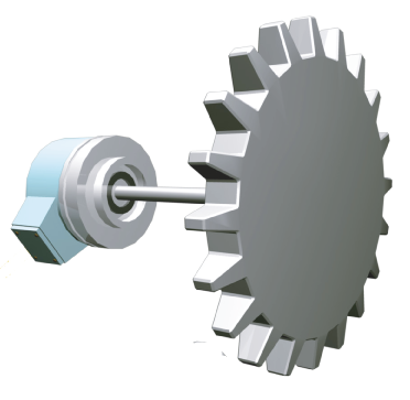
SIL certified safety encoder
+
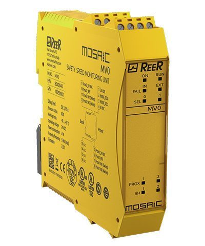
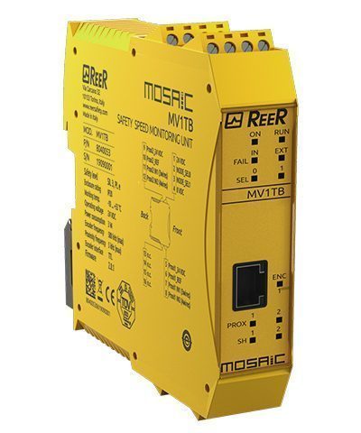
Safety speed monitoring units
MV1 or MV2
=
SIL 3 – PL e – Cat. 4
The Encoder is a safety related sensor SIL certified.
The Mosaic controller (MV1 or MV2) monitor:
- The information provided by the sensor
- Failures on the connecting cables (short circuit, open circuit, power supply failure)
Loss of mechanical coupling between the motor shaft and the encoder cannot be detected by the safety module. The coupling system shall be designed, constructed and validated as specified in Table D8 of the IEC 61800-5-2:2016 standard in order to exclude the fault due loss of mechanical fastening of the encoder.
The fault exclusion must be justifiable under all expected industrial environments including temperature, pressure, vibration, pollution, corrosive atmosphere etc.
Mosaic safety speed monitoring units identify the disconnection or short circuit of the encoder connection cables through different methods:
- For encoders with Sin/Cos output signal, the Mosaic speed monitor units continuous checking of the equation: sin2x + cos2x = 1 allows us to identify in any moment the coherence of the 2 input signals.
- For encoders with digital interfaces (TTL, HTL), when there is no movement, it is not possible to check continuously and safely the consistency of the output signals. It is therefore necessary to refer to the encoder documentation to check which is the safety level that can be reached for the control of the stationary axis (STO).
Note: if the safety integrity level of the encoder is SIL 2, then the result of the combination (Encoder + MV1 or MV2) will be SIL 2 – PL d.
Normal (non-safety) encoder TTL or HTL or Sin/Cos
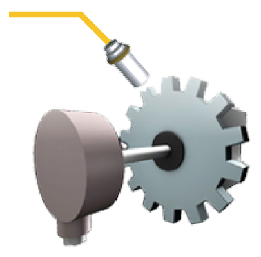
Normal (non-safety) encoder TTL
or HTL or Sin/Cos
+
1 Proximity
+
Safety speed monitoring units
MV1 or MV2
=
Up to: SIL 3 – PL e – Cat. 3
The two non-safety related sensors composes a dual-channel subsystem.
The Mosaic controller (MV1 or MV2) monitor:
- The information provided by the two sensors (e.g., deviation between the two measured values)
- Failures on the connecting cables (short circuit, open circuit, power supply failure)
The subsystem DCavg = 90% (medium).
The mechanical coupling of the encoder shall be designed, constructed and validated as specified in IEC 61800-5-2:2016 standard in order to exclude the fault due loss of mechanical fastening of the encoder.
Mechanical coupling faults of the Sensor / Phonic Wheel combination must be excluded as well by means of a suitable fixing solution.
The dual channel solution forms a Cat. 3.
The two channels are not homogeneous as the two sensors are of different technology. This reduces the possibility of common cause failures by improving the CCF (Common Cause Failure) factor score
For the calculation of the PL, it is necessary to know the MTTFD values of both sensors.
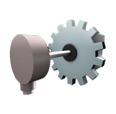
2 Proximity
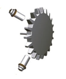
2 Proximity
+
Safety speed monitoring unit
MV0
=
Up to: SIL 3 – PL e – Cat. 3
The two Proximity non-safety related sensors creates a dual-channel subsystem.
- The two Proximity sensors shall be installed so that to generate interleaved signals.
- The Mosaic module (MV0) verifies that the two sensors measure the same speed. Failure of one of the two channels (electrical or mechanical) causes a difference in the values measured by the controller which generates an alarm signal.
Failures on the connecting cables are also detected - Loosening or loss of mechanical coupling of the phonic wheel to the motor must be avoided by means of suitable fixing solutions.
If the above conditions are fulfilled, the subsystem DCavg = 90% (medium).
The dual channel solution forms a Cat. 3 subsystem.
The two channels are homogeneous as the two sensors are of the same technology. This aspect requires more precautions to achieve the minimum score (65) of the CCF factor than the Encoder + Proximity solution.
In this case it is necessary more attention in the wiring layout, in the choice of power supplies, in the quality of the cables (EMC susceptibility). It is necessary to ensure that the sensors always work within the limits of temperature, humidity and vibrations specified in the data sheet.
For the calculation of the PL, it is necessary to know the MTTFD values of the sensors.
2 Normal (non-safety) encoder TTL or HTL or Sin/Cos

2 Normal (non-safety) encoder TTL
or HTL or Sin/Cos
+
Safety speed monitoring units
MV1 or MV2
=
Up to: SIL 3 – PL e – Cat. 3
The two non-safety related sensors composes a dual-channel system.
- The Mosaic modules (MV1 or MV2) verifies that the two sensors measure the same speed. Failure of one of the two channels (electrical or mechanical) causes a difference in the values measured by the controller which generates an alarm signal.
- Loss of mechanical coupling between the motor shaft and the encoder cannot be detected by the safety module. The coupling system shall be designed, constructed and validated as specified in Table D8 of the IEC 61800-5-2:2016 standard in order to exclude the fault due loss of mechanical fastening of the encoder.
The subsystem DCavg = 90% (diagnostic coverage = medium). The dual channel solution forms a Cat. 3
The two channels are homogeneous as the two sensors are of the same technology. This aspect requires more precautions to achieve the minimum score (65) of the CCF factor. It is necessary more attention in the wiring layout, in the choice of power supplies, in the quality of the cables (EMC susceptibility). It is necessary to ensure that the sensors always work within the limits of temperature, humidity and vibrations specified in the data sheet.
For the calculation of the PL, it is necessary to know the MTTFD values of the encoders.
Normal (non-safety) encoder TTL or HTL or Sin/Cos
Normal (non-safety) encoder TTL
or HTL or Sin/Cos
+
Safety speed monitoring unit
MV1
=
PL b – Cat. B
One single non-safety related encoder is used, thus making a single channel subsystem. No monitoring means are implemented. The Mosaic module MV1 cannot make comparisons or plausibility checks as only one single information is available.
Single failures of the encoder, regardless of the cause (electrical or mechanical), may not be detected. Faults of the connecting cable are detected. There is no diagnostic coverage, therefore DCavg = 0.
The solution is Cat.B. This limits the maximum achievable safety level to PL b.
Loosening or loss of mechanical coupling with the motor shall be avoided by means of suitable fixing solutions.
For the calculation of the PL, it is necessary to know the MTTFD values of the encoder.
The solution could reach SIL 1 -PL c- Cat.1 only if the encoder used can be considered a Well-Tried Component for safety related applications (ref. EN ISO 13849-1 and the MTTFd of the encoder is higher than 30 years. Even if theoretically possible, this solution is not recommended for the following reasons:
- ISO EN 13849-1 (§6.2.4) gives the following definition:
A “well-tried component” for a safety-related application is a component which has been either
– widely used in the past with successful results in similar applications, or
– made and verified using principles which demonstrate its suitability and reliability for safety related applications.
The decision to accept a particular component as being “well-tried” depends on the application. Example, a position switch with positive opening contacts can be well tested for a machine tool and at the same time inappropriate for application in the food industry. - Complex electronic components (e.g., PLC, microprocessor, application-specific integrated circuit) cannot be considered as equivalent to “well tried”.
- Table D.3 of ISO EN 13849-2 supply a list of “well-tried” components.
Encoders are not comprised in the list of “well-tried” components - An encoder may be declared as well-tried for safety related purposes in a given application, if the user of the encoder is able to demonstrate and document its correct behaviour and high reliability under all environmental conditions that can be assumed for the entire mission time of the device, for a sufficient quantity of parts and for a suitably long time.
1 proximity
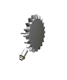
1 proximity
+
Safety speed monitoring unit
MV0
=
PL b – Cat. B
The proximity must have two antivalents outputs.
This is a single channel subsystem because one single non-safety related proximity is used. No monitoring means are implemented. The controller cannot make comparisons or plausibility checks, as only one single information is available.
Single failures of the channel, regardless of the cause (electrical or mechanical), may not be detected. Some faults of the connecting cable are detected. There is no diagnostic coverage, therefore DCavg = 0.
The solution is Cat.B. This limits the maximum achievable safety level to PL b.
Loosening or loss of mechanical coupling with the motor shall be avoided by means of suitable fixing solutions.
For the calculation of the PL, it is necessary to know the MTTFD value of the sensor.
Warning: When using phonic wheels, reading error may occur due to sensor hysteresis. If the phonic wheel stops at a position where the part detected by the sensor is at the limit (right or left) of the detectable part (e.g., tooth of the wheel), the system may still perform counts.
The solution could reach SIL 1 -PL c- Cat.1 only if the proximity used can be considered a Well-Tried Component for safety related applications (ref. EN ISO 13849-1 and the MTTFD of the proximity is higher than 30 years. Even if theoretically possible, this solution is not recommended for the same reasons of the previous point. As indicated for the encoder is also true for the proximity.
General safety principles for all combinations
The sensors shall be fixed, installed, and wired in accordance with the sensor manufacturer’s instructions.
Observe the basic mechanical and electrical safety principles (only for parts not covered by the sensor manufacturer user manual).
- Mechanical
– Correct dimensioning and shaping
– Proper selection, combination, arrangements, assembly, and installation of components/system
– Proper fastening - Electrical
– Proper selection, combination, arrangements, assembly and installation of components/system
– Correct protective bonding
– Withstanding environmental conditions
– Secure fixing of input devices
– Protection of the control circuit Failure mode orientation.
Additional safety principles for safety integrity level combinations SIL1 – PL c, SIL2 – PL d, SIL 3 – PL e
Observe the well-tried mechanical and electrical safety principles (only for parts not covered by the sensor manufacturer).
- Mechanical:
– Over dimensioning /safety factor
– Safe position
– Careful selection, combination, arrangement, assembly and installation of components/system related to the application
– Careful selection of fastening related to the application
– Limited range of force and similar parameters
– Limited range of speed and similar parameters - Electrical
– Fault avoidance in cables
– Limitation of electrical parameters
– No undefined states
– Oriented failure mode
– Minimizing possibility of faults

