

 Italiano
 English
 Deutsch
 Português
 简体中文
简体中文 한국어
한국어IEC 62061 Safety of machinery
Functional safety of safety-related electrical, electronic and programmable electronic control system
IEC 62061 is derived from IEC 61508 – Functional safety of safety-related electric/electronic/programmable electronic control systems.
IEC 62061 retains the features of IEC 61508, but simplifies safety requirements (both hardware and software) adapting them to the specific needs of industrial machinery.
Safety requirements are considered only for “high demand mode”, i.e. request of the safety function greater than once a year.
Management of functional Safety
All design aspects needed to attain the required level of functional safety, starting from assignment of the safety requirements specifications to the design management, to validation up to the instructions for safe use, shall be decided and defined before initiating the design.
Each design shall have its own Functional Safety Plan properly written, documented and duly updated as necessary. The Functional Safety Plan shall identify individuals, departements and resources needed for design and implementation of the safety system.
Safety Integrity Level (SIL )
A Safety Control System (SCS), in order to be suitable to perform the assigned safety function in the specified operating conditions and all the way through the mission time, shall have some degree or level of safety integrity (SIL). Three levels are defined, where safety integrity level 3 has the highest level of safety integrity and safety integrity level 1 has the lowest.
The SIL must be defined for each safety-related function resulting from risk analysis.
For each safety function a methodology is given for:
- The allocation of the Safety Integrity Level (SIL)
- The assignment of the safety requirements specification (SRS) and functional requirements specifications
- The design of the SCS implementing the safety function
- The validation of the SCS
SIL allocation
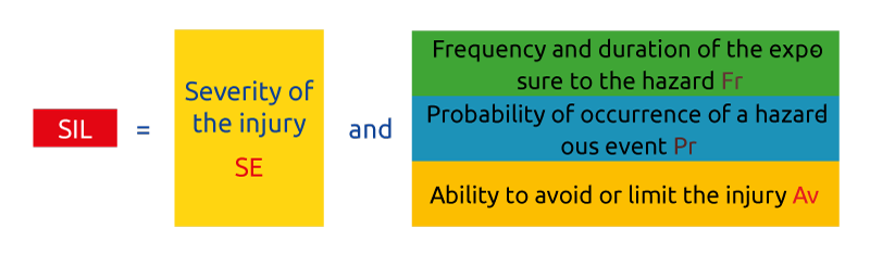
A method for SIL allocation is given in Annex A (although the Standard accepts in addition the techniques described in IEC 61508-5). According to Annex A, The SIL is determined by the following risk parameters:
- Severity of the injury -Se
- Probability of occurrence of such injury
The probability of occurrence of the injury beeing a function of:
- frequency and duration of the exposure to the hazard, Fr
- probability of occurrence of a hazardous event Pr
- ability to avoid or limit the injury, Av
It comes that for each identified hazard the the following parameters must be assessed:
- Degree of severity (Se) of the harm
- Frequency and time (Fr) of exposure to the hazard
- Probability of occurrence of the dangerous event (Pr) associated to each machine operating mode
- Possibility to avoid the hazard (Av). The more difficult it is to avoid the hazard the higher is the number representing AV
The severity is decided on the basis of the consequences of an injury
| Consequences | Severity (Se) |
| Irreversible: death, loosing an eye or arm | 4 |
| Irreversible: broken limb(s), loosing a finger(s) | 3 |
| Reversible: requiring attention from a medical practitioner | 2 |
| Reversible: requiring first aid | 1 |
Table A1 – Severity (Se) classification
- The average interval between exposures and therefore the average frequency of exposure is estimated by considering the following aspects:
– all modes of use (normal operation, maintenance)
– the nature of access(manual feed of materials, settings) - Time spent in the hazard zone
- Frequency of access
| Frequency and duration of exposure (Fr) classification | ||
| Frequency of exposure | Frequency, Fr | |
| Durationof exposure ≥ 10 min | Durationof exposure < 10 min | |
| ≥ 1 per h | 5 | 5 |
| < 1 per h to ≥ 1 per day | 5 | 4 |
| < 1 per day to ≥ 1 per 2 weeks | 4 | 3 |
| < 1 per 2 weeks to ≥ 1 per year | 3 | 2 |
| < 1 per year | 2 | 1 |
Table A2 – Frequency and duration of the exposure (Fr)
This parameter can be estimated by taking into account the human behaviour (stress, skills, machine complexity) with regard to interaction with the parts of the machine relevant to the hazard.
Very high probability of occurrence of a hazardous event should be selected to consider the worst case.
For any lower values to be used, high level of user competences and well-defined knowledge of the application are required.
| Probability of occurrence | Probability (Pr) |
| Very high | 5 |
| Likely | 4 |
| Possible | 3 |
| Rerely | 2 |
| Negligible | 1 |
Table A3 – Probability (Pr) classification
Takes into account:
- Sudden, fast or slow speed of appearance of the hazardous event
- Spatial possibility to withdraw from the hazard
- The nature of the component
- Possibility of recognition of a hazard
| Probability of avoiding or limiting harm (Av) | |
| Impossible | 5 |
| Rarely | 3 |
| Probable | 1 |
Table A4 – Probability of avoiding or limiting harm (Av) classification
Warning: the choice probable should be selected only f the hazard is clearly recognizable and if there is sufficient time to take counteractions or to leave the hazardous area.
The sum of the scores for the attributes of frequency, probability and avoidance provides the probability class (Cl) of the hazard:
Cl = Fr + Pr + Av
The following SIL allocation matrix, will help finding the SIL to be assigned to each safety–related function by cross-referencing on the matrix the actual Cl to the identified degree of severity (Se) identified.
Table A.6 – Matrix for SIL assignment
| Consequences | Severity | Class CL | ||||
| 4 | 5-7 | 8-10 | 11-13 | 14-15 | ||
| Dead, loss of an eye or an arm | 4 | SIL 2 | SIL 2 | SIL 2 | SIL 3 | SIL 3 |
| Irreversible: loss of finger | 3 | OM | SIL 1 | SIL 2 | SIL 3 | |
| Reversible: medical intervention | 2 | OM | SIL 1 | SIL 2 | ||
| Reversible: emergency room | 1 | OM | SIL1 | |||
Table 3 of IEC 62061
Assignment of the safety requirements specification (SRS) and functional requirements specifications
Safety requirements specification (SRS) must include at least the following machine characteristics:
- Cycle time
– response time performance
– environmental conditions
– switching frequency and duty cycle for electromechanical devices, if used.
Man-machine interactions
Machine behavior under normal working conditions
Required reaction of the safety function
Functional requirements specification shall describe details of each safety function, in particular:
- Description of the safety function
- Conditions of reset and conditions of re-starting after actuation of the
- Safety function
- Response time
Interfaces of the safety function with the other parts of the machine control system - Operating mode of the machine in which the safety function shall be active or disabled
Design process of an SCS
Each safety function shall be described in terms of:
- Operational requirements (mode of operation, cycle time, environmental conditions, response time, type of interface with other components or subsystems, EMC level, etc.)
- Safety requirements (SIL).
Each safety-related function shall be broken down into subfunctions, e.g. subfunction for input signals, subfunction for data processing, subfunction for output signals.
A subsystem is than associated to each subfunction.
Subsystems may be made of components of any technology, electrical, electronic, pneumatic, hydraulic, interconnected each another. Single components are called subsystem elements.
The technical implementation of a SCS will therefore assume a typical structure as shown in the figure (example of an access control implemented via a photoelectric barrier).
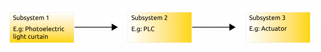
Fig. 13 – Typical structure of a SCS
An SCS can implement more safety functions. Each safety function can be made of several subsystems. A subsystem can share more subfunctions
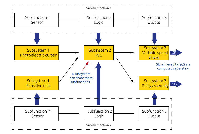
Fig. 14 – General structure of an SCS
If a subsystem shares safety functions of different safety integrity levels, its hardware and software shall be treated as requiring the highest safety integrity level.
If a subsystem implements both safety functions and other functions, then all its hardware and software shall be treated as safety-related unless the safety functions and other functions are sufficiently independent.
If digital data communication is used as a part of an SCS, it shall satisfy the relevant requirements for functional safety fieldbuses (IEC 61784-3) in accordance with the SIL target of the safety function.
Use of a pre-designed subsystem
it is possible to combine subsystems designed with this standard with subsystems designed with other safety standards. Table 4 of IEC 62061 provides a correspondence with SIL or PL values of subsystems designed with other standards.
| IEC 62061 | IEC 62061 | IEC 61508 | ISO 13849 |
| PFH | SIL | at least… | at least… |
| < 10-5 | SIL 1 | SIL 1 | PL b, c |
| < 10-6 | SIL 2 | SIL 2 | PL d |
| < 10-7 | SIL 3 | SIL 3 | PL e |
Table S4 Required SIL and PFH of pre-designed subsystems
Column IEC 61508 includes SIL-based standards that fulfil the same architectural constraints, such as IEC 61800-5-2 and IEC 60947-5-3.
It is not possible to identify a perfect one-to-one correspondence between PL and SIL; however, it is possible to compare the probabilistic part of PL and SIL because they use the same concept to define the degree of resistance to failures, i.e. the PFH, even if it is possible to compare the ranges but not the exact values because the calculation methods used are not the same in both standards.
Moreover, some restrictions are imposed:
- PLb does not correspond to SIL1 in case of a Category B structure.
- No correspondence can be assumed between IEC 62061 and IEC 61511 (all parts) or ISO 26262
IEC 61508 is the international reference standard on functional safety of electric, electronic and programmable electronic systems. This Standard consists of seven sections. The first three sections specify the safety requirements for hardware, software and safety management, the rest are of an informative nature and offer support for the correct application of the former parts.

