MTTFD value
We determine the average duration of operation, expressed in years, before a potentially dangerous random failure or «Mean Time to dangerous Failures» (MTTFD) occurs. Normally the manufacturer of the sensors does not provide data of «Performance Level» (PL) / «Probability of dangerous Failure per Hour» (PFHD) or of «Mean Time to dangerous Failures» (MTTFD) but only the value of «Mean time between failure ”(MTBF) which, in this example, we assume 54 years (real figure obtained from a manufacturer). If this value is not available, it is possible to obtain standard values from the EN ISO13849-1 Annex C. In this case it is possible to make the following assumptions
MTTF = MTBF + MTTR (Mean Time To Restoration)
«Mean time to restoration» (MTTR) or average repair time, is the time interval during which an equipment is in a state of unavailability due to a fault. The MTTR includes the time for diagnosis, the time for the arrival of the maintenance technician, the arrival of the component to be replaced and the actual repair. For electronic equipment MTTR can be considered negligible (it is not repaired, it is replaced).
MTTF≈MTBF
When the dangerous failure rate is not known, EN13849-1 allows us to assume that these are 50% of all failures, therefore:
MTTFD = 2 x MTBF
MTTFD= 2 x 54 = 108 years
This evaluation refers to the single sensor.
We now determine the value of the «Diagnostic Coverage» (DC)
The Diagnostic Coverage specifies how efficient the system is in determining its malfunctions in real time ie before another failure occurs.
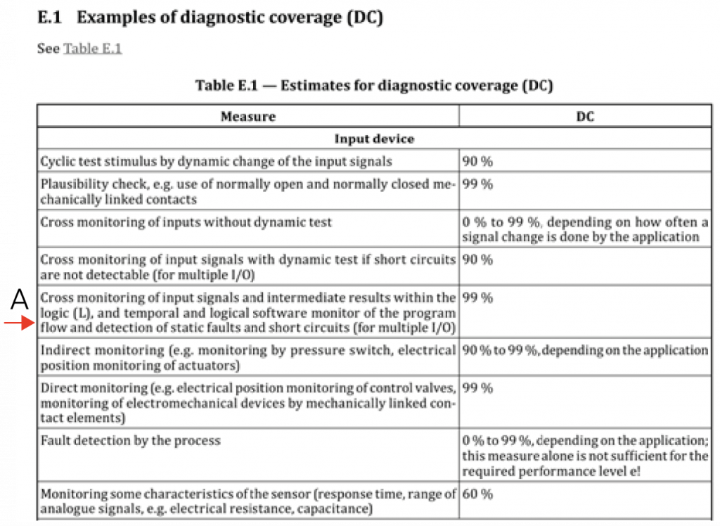
We will use the ISO 13849 Table E1 (shown right), which provides a list of 34 different diagnostic techniques that can be used to increase the fault detection capability of a circuit.
The techniques are divided into three families (input circuits, signal processing logic and output circuits).
A percentage score between 0% and 99% is assigned for each technique.
Mosaic MA4 and MA2 perform cross monitoring [A] as required by the table, then the system reaches 99% DC.
This is still not enough for the system to reach Category 4.
Accumulated faults
To obtain the Category 4, Table 10 of ISO 13849-1 (see previous page) requires the DC to be High (99%) and includes the accumulation of faults, e.g. multiple faults can occur, one after the other, without degrades the safety function.
The single fault must be detected when it occurs or before the next request from the safety function. If this is not possible, an accumulation of undetected faults must not lead to the loss of the safety function.
To meet this requirement, the choice of sensors or how to use them also matters.
- A sensor with 0-10 V output has the minimum value at 0 VDC which is indistinguishable from a short circuit at 0 VDC. Furthermore both sensors could have this type of fault resulting in an accumulation of faults.
- Sensors with 0-20 mA current output follow the same logic but with a dangerous fault represented by a open circuit (for example a disconnected cable).
In safety applications, if we want to reach Category 4, these type of sensors must be avoided or a threshold must be programmed for which below a certain value, for example 0.5 VDC or 2 mA, the system reacts as if to a fault . With the Mosaic system, for example, it is possible to configure the operating parameters through the MSD software to increase the DC. Intermediate controls can be implemented such as:
- Measurement error between the 2 sensors.
- Time control of out of range.
An important aspect remains regarding the diagnostic coverage and the accumulation of faults. The case where the sensor output value does not change for a period of time.
Let’s assume that sensors, for example for temperature, measure the same value for a long time, always transmitting the same current value, e.g. 5 mA. One of the possible faults that could occur is that in which both sensors, in sequence, break, always transmitting the same current value. Such a fault could not be detected by the safety system.
To be sure to also detect this type of accumulated faults, it is necessary to carry out dynamic tests, for example by varying the temperature in the part of the machine to which the sensors are connected, with a predetermined frequency (for example 4 times per hour). This type of test is mandatory for category 4.
To conclude these assessments on accumulated failures, we must point out:
- It is often impossible to force changes into a process. As for our example, it could be difficult to change the temperature of a part of the machine.
- All this is required for Category 4 ONLY.
- The use of adequately sensors and thresholds to avoid short circuits or undetected open circuits is also important in the calculation of CCFs, described below.
If we want to obtain a Category 4, we must increase the Diagnostic Coverage (DC) or at least verify that the use of our safety system is the best possible. There are methods to evaluate what the time interval must be between 2 successive changes in the values measured by the sensors:
- Statistical mathematical evaluations of the reliability characteristics of the sensors used and their configuration. There are established but complex calculation methods to analyse them in this guide. However, the use of complex mathematical tools does not guarantee the accuracy of the result.
- Consider the practical application of the sensors and aim for a significantly lower test interval than the duration of inactivity of the sensors. Or carry out a test before using the machine and the need for the safety function.
The ultimate goal is that the accumulation of faults, even not detected, never leads to the loss of the safety function. This is the mandatory requirement of Category 4, it is often impossible to fully comply.
This is the fault resulting from one or more events that causes the simultaneous malfunction of the channels of a two or more channel system.
It provides an indication of the degree of operational independence of the channels of a redundant system.
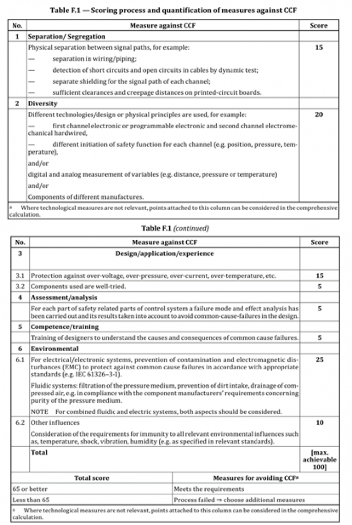
Using the table F1 (shown on the right) of the ISO 13849 standard, a score is assigned in relation to any measure against common cause failures. The maximum achievable score is 100.
The calculation and verifications are common for all categories.
1. Separation / Segregation
Use of shielded cables – With the use of analog outputs, shielded cables are already normally used, and it is the single cable that is shielded.
Detection of faults such as short circuits or open circuits – The detection characteristics of analog signals, current (0 … 20 mA) or voltage (0 … 10 V) allow to satisfy the indicated measurements.
This can be done easily by excluding values such as 0 V or
0 mA. So it’s easy to get the 15 points.
2. Diversity
Use of different sensors – For example, with the Mosaic MA2 MA4 modules, 2 sensors can be used not only with different full scale but, even, with different types of outputs (voltage or current).
It’s easy to get the 20 points.
3. Design / Application / Experience
Use of protections – By inserting the appropriate and necessary protections (Over-Voltage and Over-Current) 15 points can be obtained.
Use of well tried components – Devices with analog output are not among the well tried components (EN 13849-2 table D.4). So 0 points.
4. Evaluation / Analysis
Failure mode and effect analysis (FMEA) analyzes are required.
This type of analyses would require a lot of time, for this measure we assign 0 points by not carrying out any activity.
NOTE: However, a FMEA is not necessarily a mathematical calculation of the probability of risk, but it is an analysis of all types of failure to evaluate their effects. An evaluation of this type must however be carried out when choosing and installing sensors, so it might be worthwhile to document it and get the few 5 points it deserves.
5. Competence / Training
Considering the designers prepared to understand the generation of CCFs and their consequences, we assign 5 points.
6. Environment
The system must be immune to the effects of the surrounding environment, such as dirt. Furthermore, the system must be immune to EMC disturbances, in particular to EMC disturbances generating CCF (Common mode and / or differential disturbances). Only if it can be proven (also documented with tests), we have 25 points.
All other environmental conditions (temperature, humidity, vibrations…) must be taken into consideration. Only if immunity can be demonstrated, we have 10 points.
At least 65 points must be obtained. It is quite clear that the conditions for reaching Category 3 are quite easy. The achievement of System Category 4 (not to be confused with that of the module) is more critical due to the difficulty of detecting the accumulation of faults.
Basically:
- If it is demonstrable that DC = 99% and the accumulation of faults is detected, the requirements of Category 4 are met.
- In the event that it is demonstrable that DC> 90% and the accumulation of faults is not detected, the requirements of Category 3 are met.
Conclusion
Based on table K1 of EN 13849-1, the safety function in our example, with 62 years sensor MTTFD, high DCavg but, for example, without the conditions required by Category 4 because we are unable to test sensors at regular intervals, PLe is reached (green box).
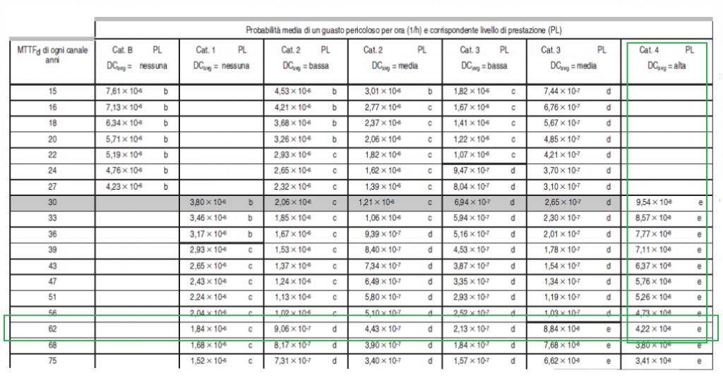
From the table, the sensor subsystem will have:
PL=e with PFHD=4,22×10⁻⁸
the other component of th e safety system is Mosaic.
From the Mosaic report a combination of M1S master module + MA4 analog module have the value:
PFHD=2,97×10⁻⁸
To calculate the total PL we have to add the PFHD
PFHD total= PFHD_sensor + PFHD_Mosaic = 4,22×10⁻⁸ + 2,97×10-8 = 7,29×10⁻⁸
Always PL=e
Use of not safety sensors for safety functions according to EN IEC 62061
The same considerations can also be repeated with this standard for process automation. However, the calculation and analysis methods are much more complex.
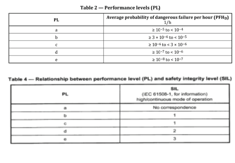
For a simplified approach it is possible to refer to this table of EN ISO 13849 which proposes a relationship between the final values achieved